Category:Diagrams of power plants
Jump to navigation
Jump to search
Subcategories
This category has the following 3 subcategories, out of 3 total.
Media in category "Diagrams of power plants"
The following 98 files are in this category, out of 98 total.
-
 111. Central London Railway - Plan of Power Station.jpg 2,236 × 1,830; 562 KB
-
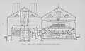 112. Central London Railway - Cross-section of Power Station.jpg 2,858 × 1,713; 801 KB
-
 113. Glasgow Corporation Tramways - Plan of Power Station.jpg 2,720 × 2,014; 1.15 MB
-
 114. Glasgow Corporation Tramways - Cross-section of Power Station.jpg 1,723 × 1,157; 437 KB
-
 115. Bristol Tramways - Cross-section of Power Station.jpg 1,702 × 2,857; 892 KB
-
 116. Dublin United Tramways - Cross-section of Power Station.jpg 2,851 × 1,727; 1.01 MB
-
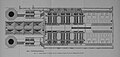 117. Arrangement of Boiler Plant of Dublin United Tramways Generating Station.jpg 3,610 × 1,717; 1.4 MB
-
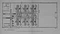 118. Plan of Engine Room of Dublin United Tramways Generating Station.jpg 3,062 × 1,745; 1.02 MB
-
 119. Design of 10,000 k.w. Power Station.jpg 2,813 × 1,836; 1.05 MB
-
 120. Design of 10,000 k.w. Power Station. Cross-section.jpg 1,861 × 1,416; 577 KB
-
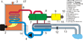
 Bhkw schema hu.png 622 × 550; 39 KB
-
 Bhkw schema.png 622 × 550; 16 KB
-
 Boiling Water Reactor 01-ja.svg 900 × 600; 75 KB
-
 Boiling Water Reactor 01.svg 900 × 600; 113 KB
-
 Brockhaus-Efron Power Plants 3.jpg 1,068 × 1,711; 230 KB
-
 Brockhaus-Efron Power Plants 6.jpg 1,698 × 1,136; 444 KB
-
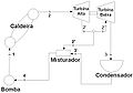 Ciclo rankine AAA.jpg 680 × 477; 35 KB
-
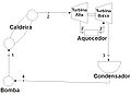 Ciclo rankine reaq.jpg 677 × 492; 32 KB
-
 Ciclo rankine.jpg 690 × 496; 25 KB
-
Combined cycle animation esp.ogv 35 s, 854 × 480; 8.5 MB
-
Combined cycle animation.ogv 58 s, 1,280 × 720; 32.71 MB
-
Combined cycle animation.webm 57 s, 1,280 × 720; 38.7 MB
-
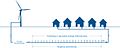
 Combined heat and power with export.JPG 825 × 556; 79 KB
-
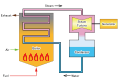
 Combustion turbine diagram.svg 860 × 393; 85 KB
-
 Dampfkreislauf.png 1,024 × 574; 144 KB
-
 DEMO power plant schematic.jpg 1,730 × 1,304; 394 KB
-
 Development and electrical distribution of water power (1908) (14760354191).jpg 2,912 × 1,916; 458 KB
-
 Development and electrical distribution of water power (1908) (14760394041).jpg 3,168 × 1,354; 577 KB
-
 Diagram of Schiller Station Mercury Vapor System.jpg 1,584 × 2,108; 872 KB
-
 Energiamuundus.png 564 × 667; 106 KB
-
 Energiefluss-Diagramm GuD-KWK-Einwellenanlage.jpg 3,000 × 1,327; 710 KB
-
 Energieverteilung01.png 1,022 × 591; 87 KB
-
 EUROfusion schematic diagram of fusion power plant.jpg 4,160 × 2,340; 3.02 MB
-
 Fast Breeder Reactor 01-ja.svg 900 × 600; 117 KB
-
 Fast Breeder Reactor 01.svg 900 × 600; 192 KB
-
 Fernwärme.jpg 1,026 × 410; 79 KB
-
 Ferwaermespeicher funktionsdiagramm.jpg 886 × 401; 196 KB
-
 Fliessbild01.png 993 × 678; 153 KB
-
 Gas Turbine Combined Cycle Generation 01-ja.svg 900 × 600; 110 KB
-
 Gas Turbine Combined Cycle Generation 01.svg 900 × 600; 170 KB
-
 Gas Turbine Generation 01-ja.svg 900 × 600; 79 KB
-
 Gas Turbine Generation 01.svg 900 × 600; 121 KB
-
 Gaskraftwerk.PNG 1,712 × 928; 39 KB
-
 HD.15.093 (11840114825).jpg 3,200 × 2,151; 360 KB
-
 HD.15.101 (11841309575).jpg 3,200 × 2,139; 419 KB
-
 HD.15.105 (11841311675).jpg 3,200 × 2,145; 328 KB
-

-
 Hybrid solar biomass plant diagram-es.png 1,000 × 446; 85 KB
-
 Hybrid solar biomass plant diagram.jpeg 985 × 439; 110 KB
-
Hydroelectric dam animation esp.ogv 1 min 3 s, 1,920 × 1,080; 26.93 MB
-
Hydroelectric dam animation.ogv 1 min 3 s, 1,248 × 702; 49.89 MB
-
 Hydroelectric dam-sv.svg 576 × 381; 37 KB
-
 Integrated Coal Gasification Combined Cycle 01-ja.svg 900 × 600; 235 KB
-
 Integrated Coal Gasification Combined Cycle 01.svg 900 × 600; 390 KB
-
 Integrated Coal Gasification Fuel Cell Combined Cycle 01-ja.svg 900 × 600; 250 KB
-
 Integrated Coal Gasification Fuel Cell Combined Cycle 01.svg 900 × 600; 399 KB
-
-

-
 Kombiprozess.png 816 × 567; 24 KB
-
 Kraftwerk Bois-Noir – elektrisches Schema de.png 1,339 × 759; 522 KB
-
 Kraftwerkstypen.svg 860 × 1,126; 355 KB
-
 Methane gas facility diagram.svg 525 × 320; 79 KB
-
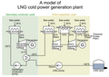 Model of LNG cold power generation plant E.PNG 900 × 640; 100 KB
-
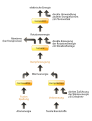
 Model of LNG cold power generation plant J.PNG 900 × 640; 90 KB
-
 Osmot1.jpg 478 × 640; 81 KB
-
 OTEC diagram.gif 559 × 417; 8 KB
-
 Power station in blocks.jpg 911 × 637; 147 KB
-
 Pressurized Water Reactor 01-ja.svg 900 × 600; 73 KB
-
 Pressurized Water Reactor 01.svg 900 × 600; 106 KB
-
 Prinzip Gas-und-Dampf-Kombikraftwerk.svg 904 × 608; 107 KB
-
 Querschnitt der Zentrale Amsteg des Kraftwerks Arniberg (1910).jpg 957 × 555; 132 KB
-
 Rankine cycle layout.png 1,850 × 1,200; 142 KB
-
 Rankine cycle layout.svg 686 × 446; 21 KB
-
 Rankineov ciklus izgled.PNG 1,850 × 1,200; 200 KB
-
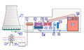
 Schema ciclo combinato.jpg 1,625 × 1,272; 384 KB
-
 Schema Dampfkraftwerk.PNG 800 × 422; 63 KB
-
 Schemat Inwestycji EEW.jpg 1,170 × 464; 50 KB
-
 Schemat inwestycji PFN.jpg 1,281 × 416; 56 KB
-
 Scientific American Volume 91 Number 18 (October 1904) (1904) (14755519722).jpg 2,876 × 1,854; 1.14 MB
-
 Spiral wound universal pressure boiler - de.png 1,600 × 1,660; 559 KB
-
 Steam Power Generation 01-ja.svg 900 × 600; 96 KB
-
 Steam Power Generation 01.svg 900 × 600; 117 KB
-
 Steam Powerplant.jpg 550 × 362; 65 KB
-
 Steam-electric power plant.PNG 400 × 240; 21 KB
-
 Superheated reheated rankine cycle.svg 1,603 × 1,420; 59 KB
-
 Thermodynamic circuit of a steam power plant based on a bled Rankine cycle.svg 1,257 × 1,233; 54 KB
-
 Thermodynamic circuit of a steam power plant based on a Carnot cycle.svg 1,547 × 1,420; 51 KB
-
 Thermodynamic circuit of a steam power plant based on a Rankine cycle.svg 1,209 × 1,420; 51 KB
-

-

-
 Thermodynamic circuit of a steam power plant.svg 2,525 × 1,833; 97 KB
-
 Turbine-Clausius-Rankine cycle 2.svg 521 × 398; 12 KB
-
 Turbine-Clausius-Rankine cycle.svg 453 × 398; 8 KB
-
 Umlaufkühlung.PNG 520 × 339; 12 KB
-
 Usinde de Bois-Noir – Schéma électrique fr.png 1,339 × 759; 585 KB
-
 Virt kraftwerk.jpg 600 × 377; 23 KB
-
 Wärmekraftwerk schematisch.png 146 × 194; 2 KB
-
 Ölkraftwerk.PNG 1,712 × 928; 38 KB


_(14760354191).jpg)
_(14760394041).jpg)


.jpg)
.jpg)
.jpg)
,_Funktionsschema_Maschinensatz.jpg)


_01-ja.svg)
_01.svg)


.jpg)


_(1904)_(14755519722).jpg)


